VRF installation is not similar to split ac installation, some important guidelines you must follow if you are planning for your VRF installation process.
Installation Flowchart
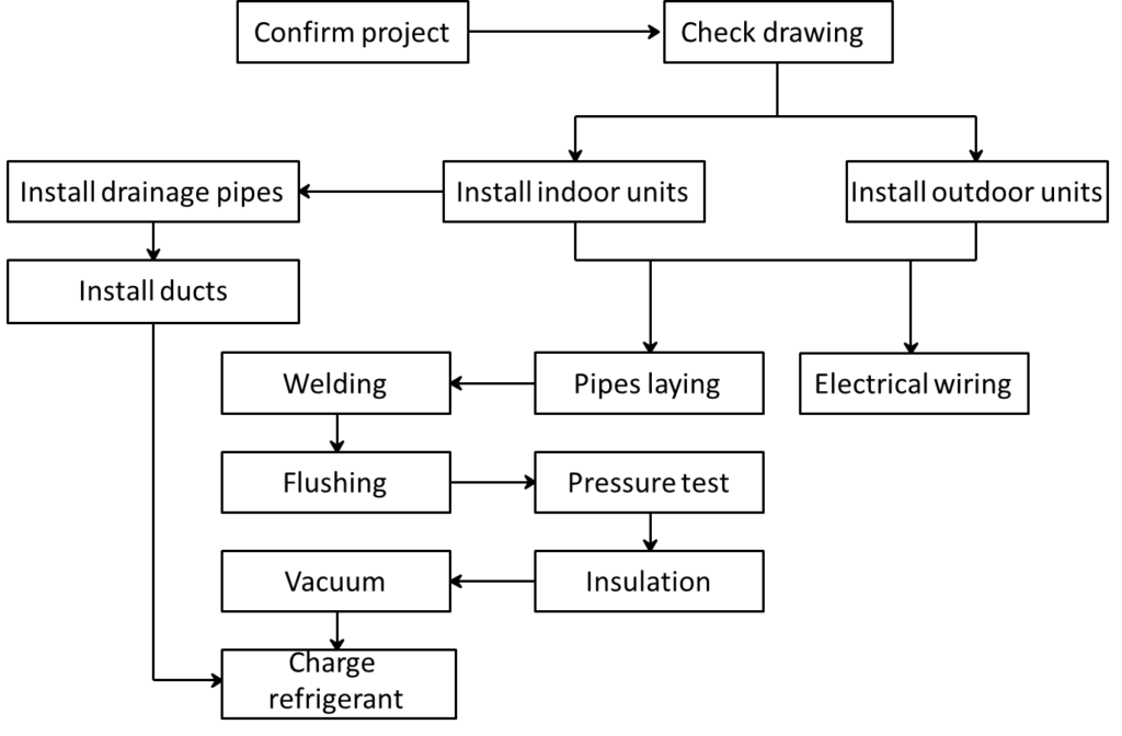
We will discuss the above processes one by one in this article.
Once pipe sizes are selected, piping routes are finalized, & indoor & outdoor unit locations are freezed, now its time to start installation process. Let’s see some important tips before
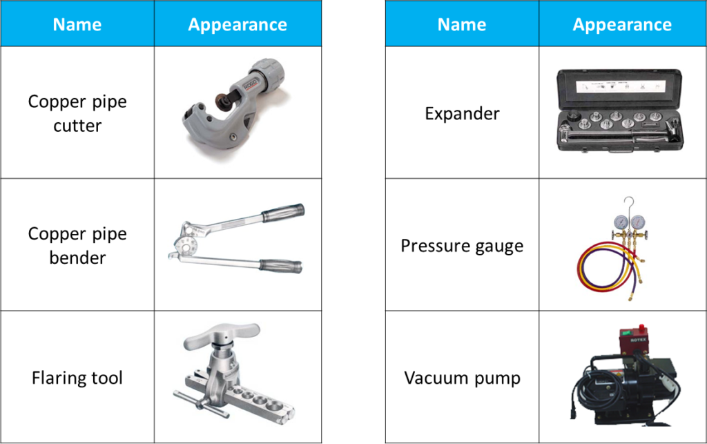
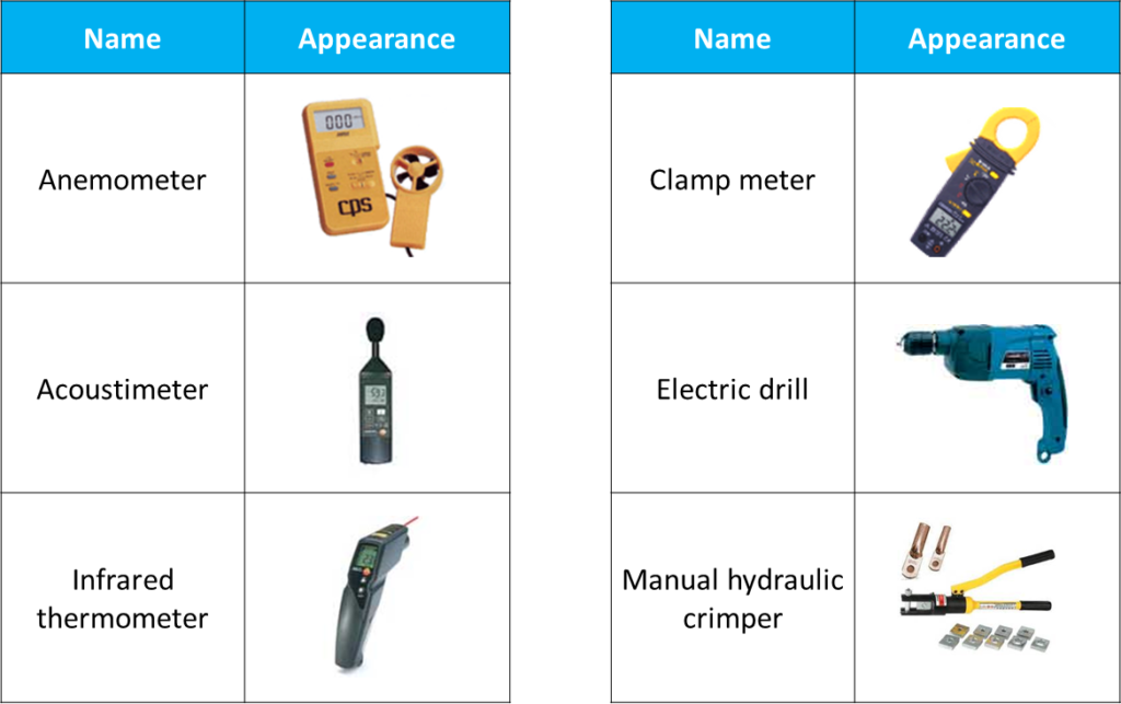
Main tools
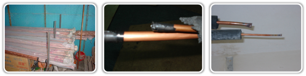
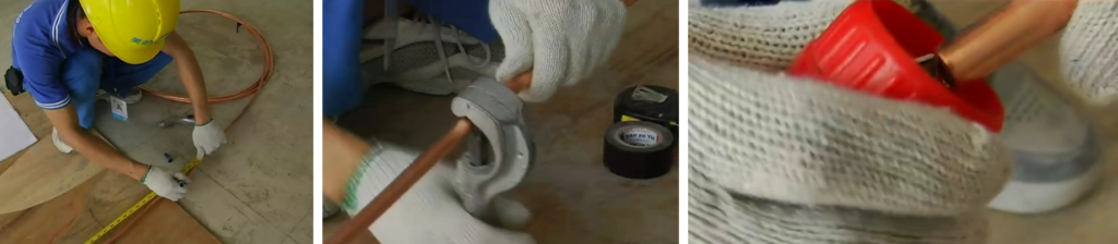
Copper Piping storage Tips
- If pipes will be used soon, nozzle should be sealed by plastic bag or tape.
- If pipes will be stored for a long time, the pipes should be charged with 0.2~0.5MPa Nitrogen and the nozzle should be sealed by welding.
- Indoor units installation
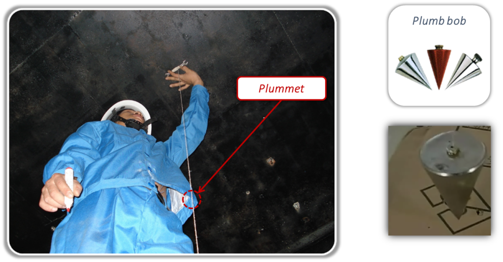
Use plumb bob to determine the location of indoor unit.
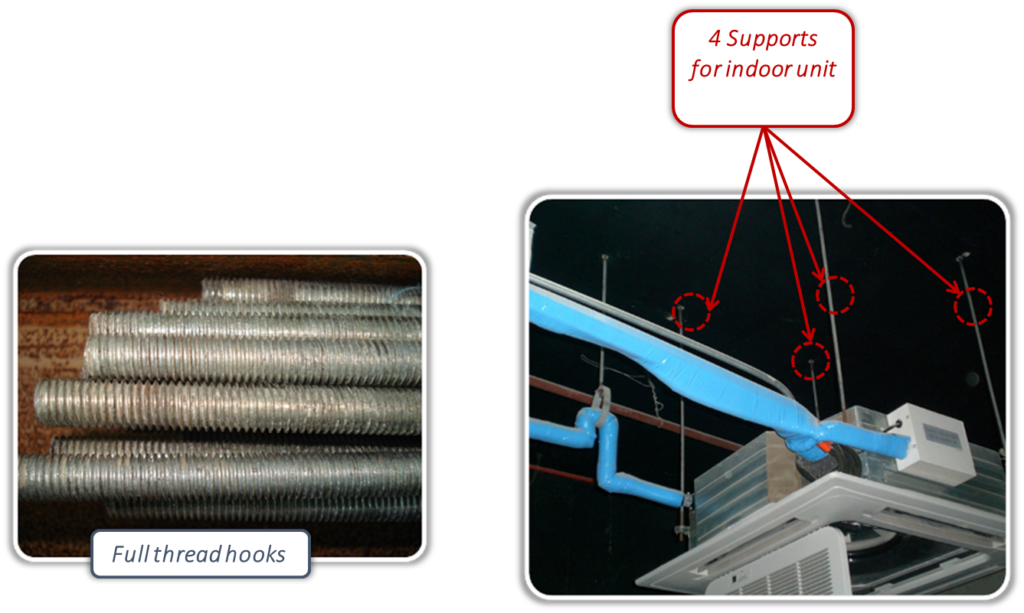
Hoisting
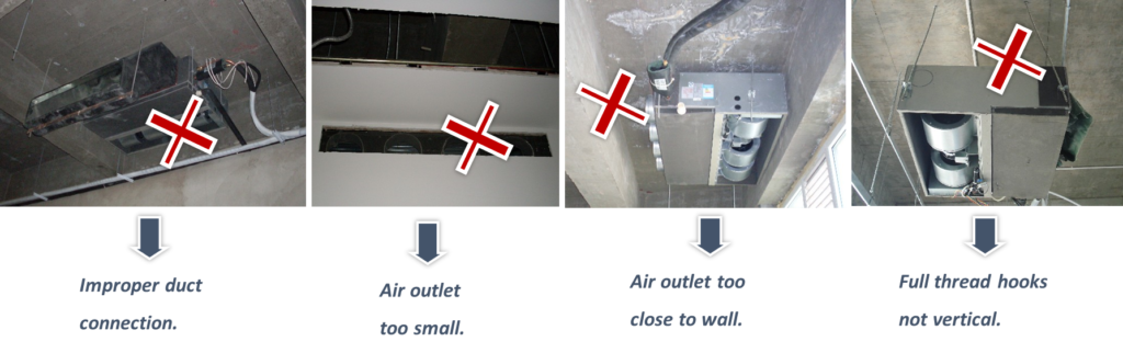
Supports must be strong enough. The supports should be full thread hooks, and their diameters should be ≥ 10mm.
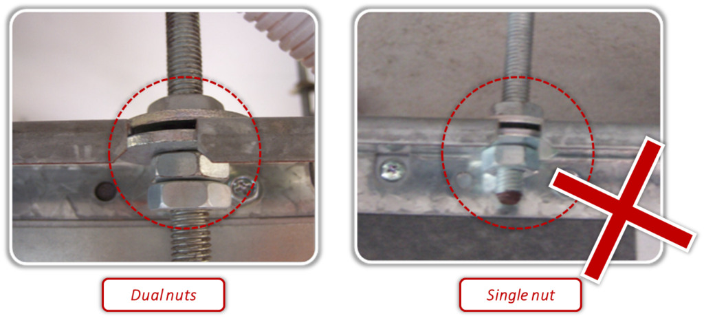
Dual nuts should be adopted to fix the indoor unit under the ceiling.
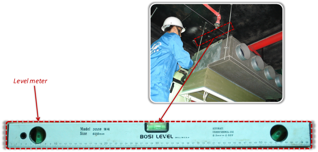
Use level meter to keep the indoor unit horizontally to reduce the running noise and avoid the condensate water spill from the water collector.
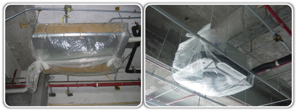
Pack the indoor unit with plastic bag after hoisting to protect them from dust entering.
Typical mistakes
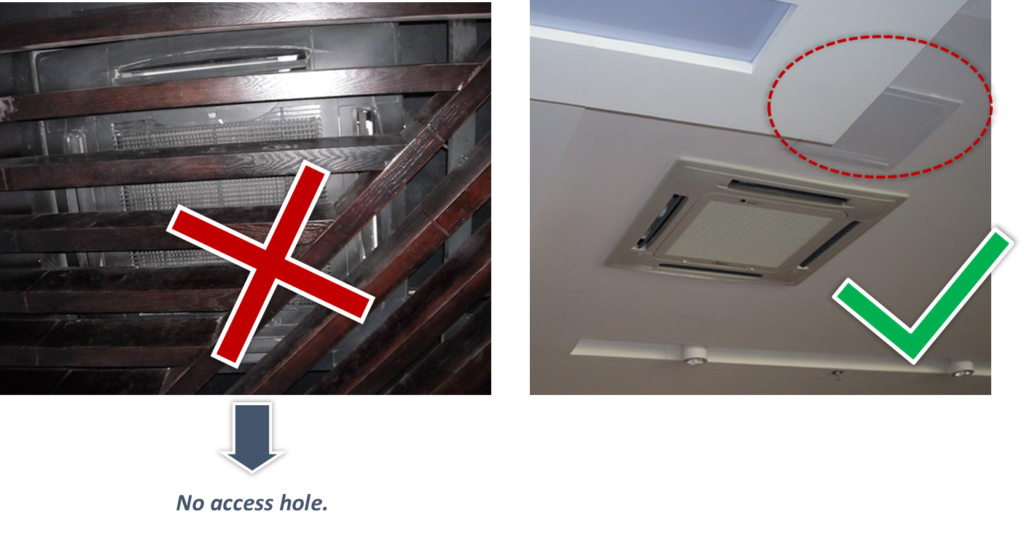
Access hole-Access hole for easy maintenance and service.
2. Outdoor units installation
Location
- Provide sufficient space around the unit for servicing and air circulation.
- Make sure the installation site withstands the unit’s weight and vibration.
- Make sure the area is well ventilated. Do NOT block any ventilation openings.
- Make sure the unit is level.
- All the outdoor units in one combination should be on the same level.
Do not install the unit in the following places:
- In potentially explosive atmospheres.
- In places where there is machinery that emits electromagnetic waves. Electromagnetic waves may disturb the control system, and cause malfunction of the equipment.
- In places where there is a risk of fire due to the leakage of flammable gases (example: thinner or gasoline), carbon fiber, ignitable dust.
- In places where corrosive gas (example: sulphurous acid gas) is produced. Corrosion of copper pipes or soldered parts may cause the refrigerant to leak.
Installation space requirements:

- Depending on the height of adjacent walls relative to the height of the units, ducting may be required to ensure proper air discharge. In the situation depicted in below figure, the vertical section of ducting should be at least H-h high.

Master and slave unit positioning
- In systems with multiple outdoor units, the units should be placed in order from largest capacity unit to smallest capacity unit. The largest capacity unit must be placed on the first branch, and be set as the master unit, while the others should be set as slave units.
- All the outdoor units in one combination should be on the same level.

Base structures
- Bases should be constructed on solid ground or on structures of sufficient strength to support the units’ weight.
- Bases should be at least 200mm high to provide sufficient access for installation of piping.
- Either steel or concrete bases may be suitable.
- bases should be completely level.
- A drainage ditch should be provided to allow drainage of condensate.

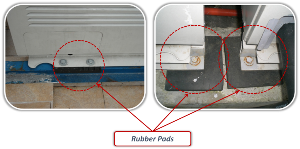
- Rubber anti-vibration pads are necessary to avoid vibration.
- Do not remove the package before commissioning
3.Piping installation
Pipe cutting
- Measure the exact length of pipes.
- Use the pipe cutter to cut the pipes.
- Use scraper to remove the copper burrs.
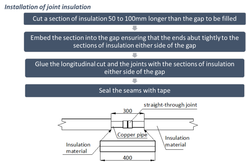
Pipe insulation
Purpose
- Prevent condensate water adhere to the gas pipe
- Protect people from hurt of high temperature
- Avoid energy loss
- To ensure unit performance and compressor lifespan.
Caution: After finishing gastight test, the insulation work should be done on the pipe connection parts and branch pipes.
Refrigerant piping insulation should be closed-cell foam of B1 fire resistance rating that can withstand a constant temperature of over 120oC and that complies with all applicable legislation.
- The insulating material should be a suitable thickness and the inner diameter should match the size of refrigerant pipes
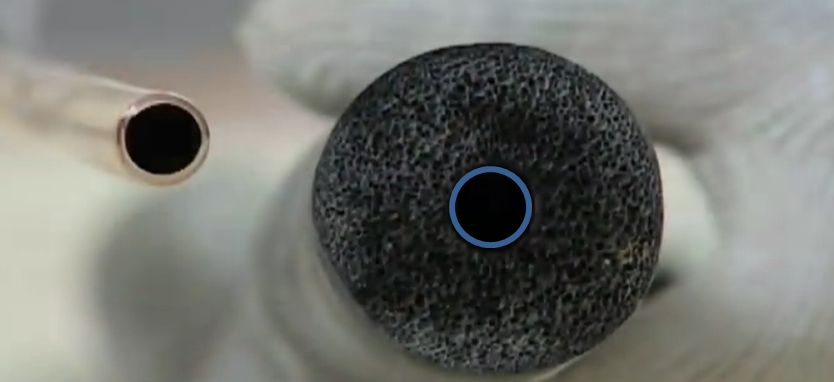
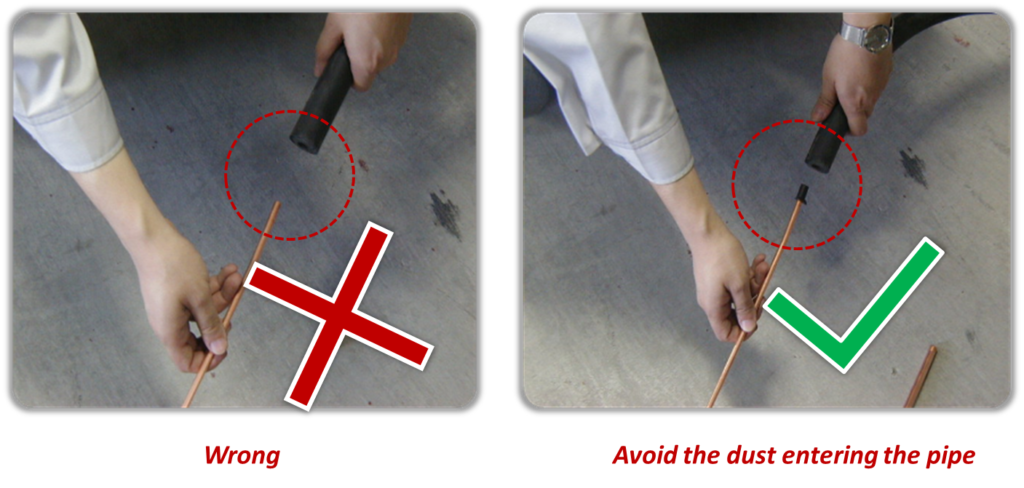
- Block the nozzle of the pipe when make it through the insulation material.
- The gap between two parts should be well insulated by additional insulation material.
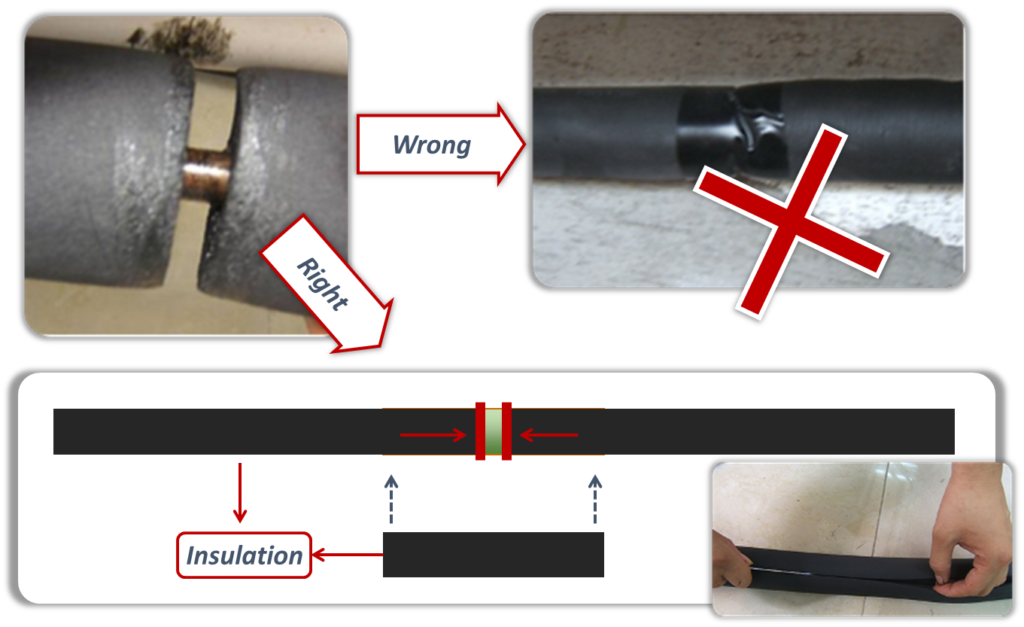
- The insulation of liquid pipe and gas pipe must be separate.
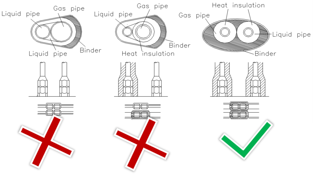
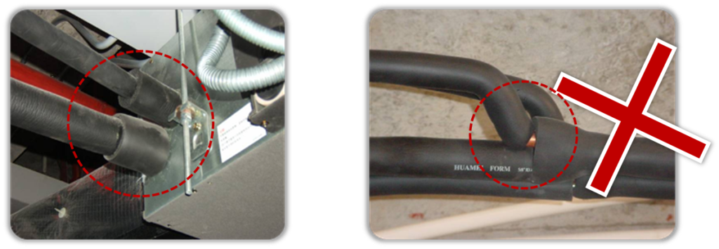
- The insulation work must be done on every part of the refrigerant pipes.
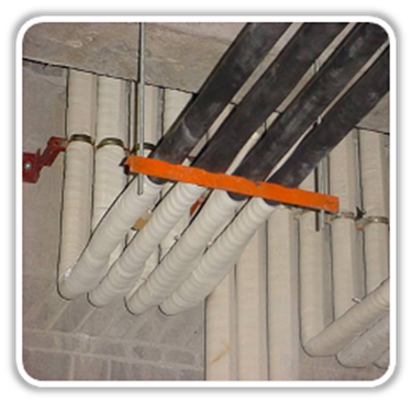
Pipe hanging
- The distance between the supports of the copper pipes
| Diameter (mm) | ≤20 | 20~40 | ≥40 |
| Distance (mm) | 1 | 1.5 | 2 |
- When the liquid pipe and gas pipe are hung up together, it is determined by the diameter of liquid pipe.
- Record the actual liquid pipe length for future reference when charging additional refrigerant.
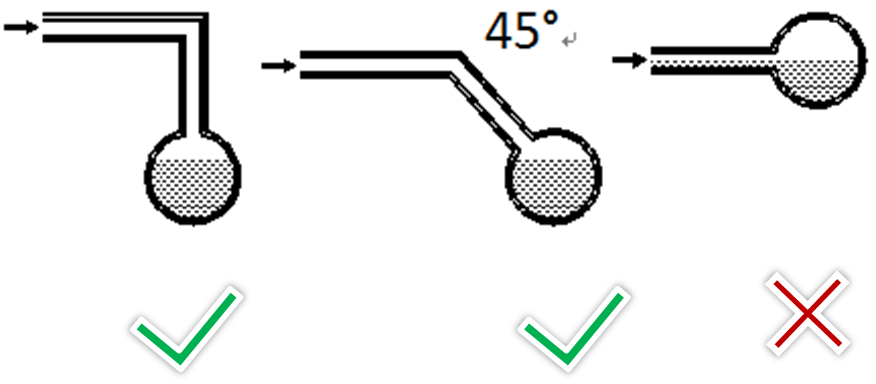
Pipe connection
- U-shaped branch of outdoor side must be installed horizontally.
- •The branch joint of indoor side can be installed horizontally or vertically.
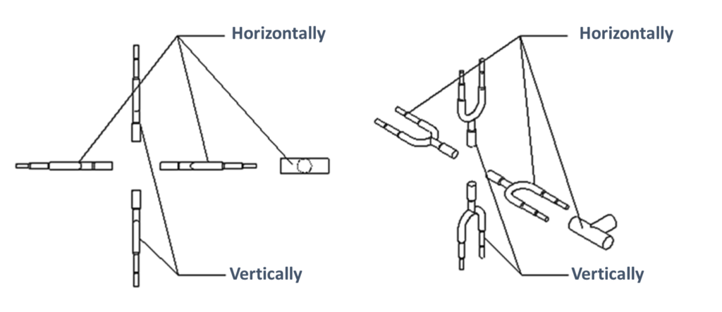
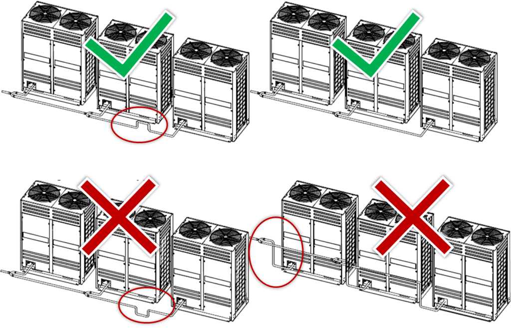
- To avoid accumulation of oil in the outdoor units, outdoor branch joints should be installed horizontally and must not be higher than the outdoor unit refrigerant outlets.
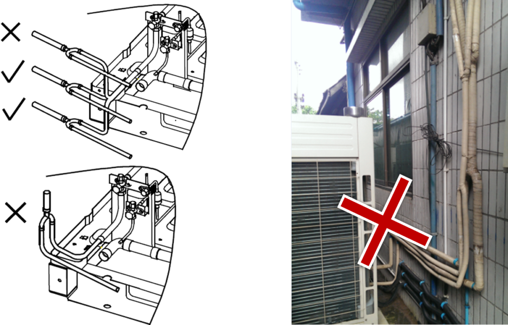
- Horizontal branch joints must be installed at an angle to the horizontal not exceeding 10o in order to avoid uneven distribution of refrigerant and possible malfunction.

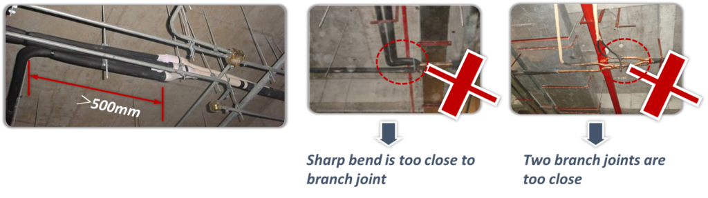
- To ensure even distribution of refrigerant, branch joints should be installed:
- More than 500mm of a 90o bend to an branch joint;
- More than 500mm of an branch joint to another branch joint;
- More than 500mm of the straight section of piping leading to an indoor units;

- Refrigerant flow through bend of branch will cause Turbulent flow, turbulent flow may cause noise and make unbalance refrigerant distribution if not enough distance is satisfied.
- Refrigerant piping connection method.
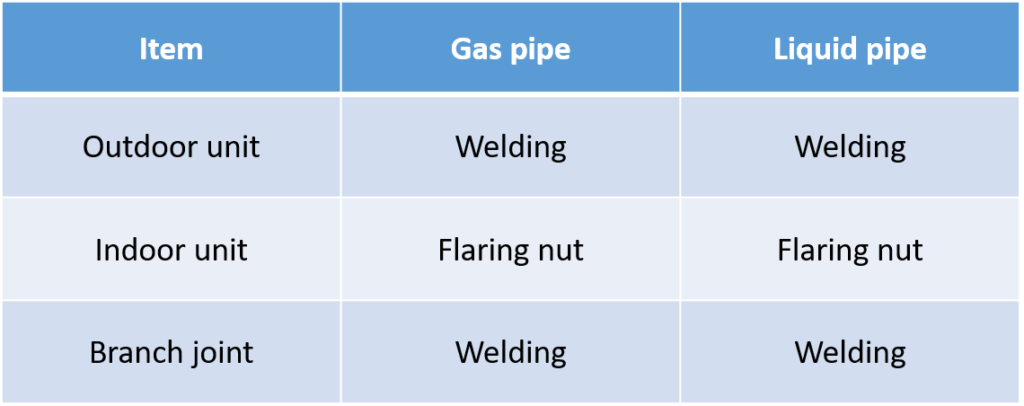
Welding
- Never flow oxygen through piping as doing so aids oxidation and could easily lead to explosion and as such is extremely dangerous.
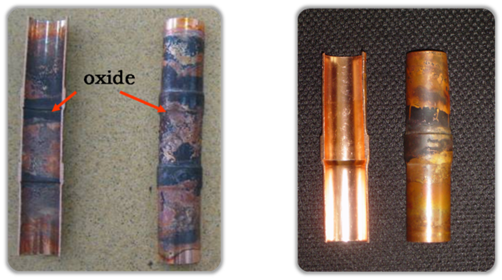
- Use a pressure reducing valve to flow nitrogen through copper piping at 0.02-0.03MPa during welding.
- Start the flow before brazing starts and ensure that the nitrogen continuously passes through the section being welded until the welding is complete and the copper has cooled down completely.

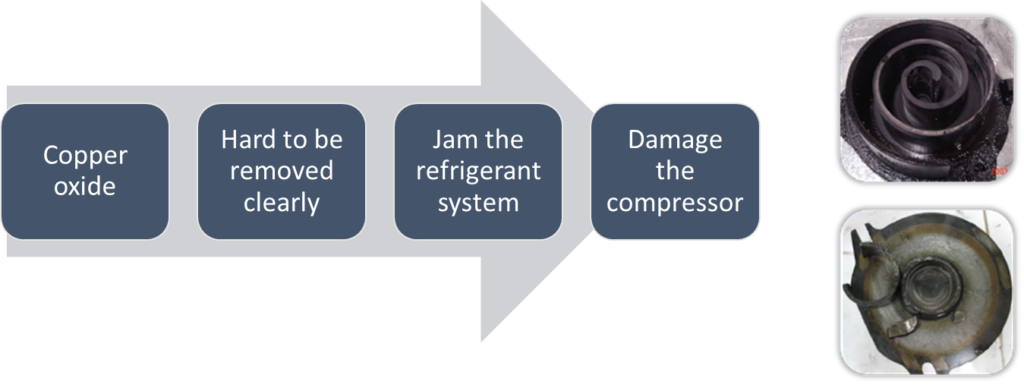
Why the Nitrogen is necessary?

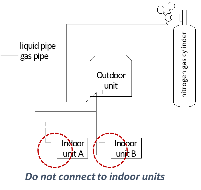
4.Flushing
Purpose: to remove dust, other particles and moisture, which could cause compressor malfunction.
- Flushing should be performed once the piping connections have been completed with the exception of the final connections to the indoor units.
- Only use nitrogen for flushing.
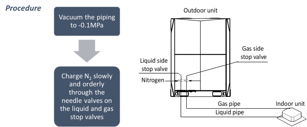
Procedure:
The liquid and gas sides can be flushed simultaneously; alternatively, one side can be flushed first and then for the other side
- Use blind plugs to block all liquid (gas) side openings, except for the opening at the indoor unit which is farthest from the outdoor units .
- Flush the pipe with 0.5 MPa Nitrogen.
- Use your hand to block the opening, when the pressure is too high to block, then remove your hand.
- Repeat the step 3 until on further dirt or moisture is emitted from the piping. Seal the opening once it has been flushed.
- Flushing the other openings in the same manner, working in sequence from the farthest indoor unit towards the outdoor unit.
- After flushing, seal all the openings.


5.Gas tightness test
Purpose: to prevent faults caused by refrigerant leakage, a gastightness test should be performed before system commission.
- Only dry nitrogen should be used for gastightness testing.
- Keep the liquid and gas stop valves fully closed.
- The piping system is complete and the indoor and outdoor units have been connected.
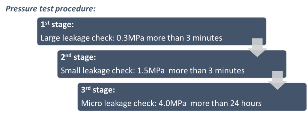
Check for micro leakages:
If there’s 1oC difference in temperature, there will be 0.01MPa difference in pressure.
Correcting formula:
Actual value
= Pressure when finish charging +(current temp. – temp. when finish charging) x 0.01MPa
Example:
- Temp. when charging N2: 24oC
- N2 pressure when charging: 3.8MPa
- Temp. after 24 hours: 22oC
- N2 pressure after 24hours
= 3.8MPa + (22oC-24oC) x 0.01MPa/oC
= 3.8MPa -0.02MPa
= 3.78MPa
If the actual pressure after 24hours is lower than 3.78MPa, you need to check leakage.
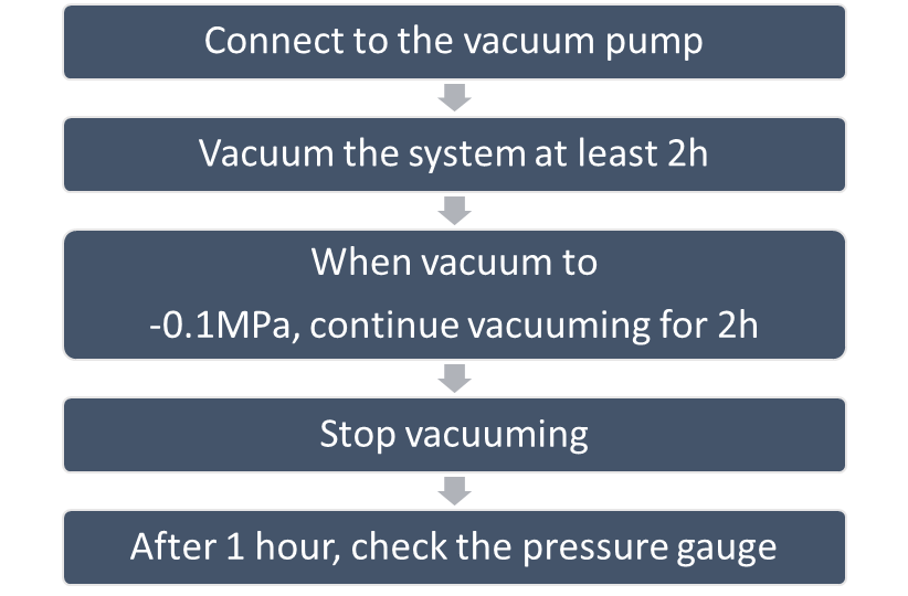
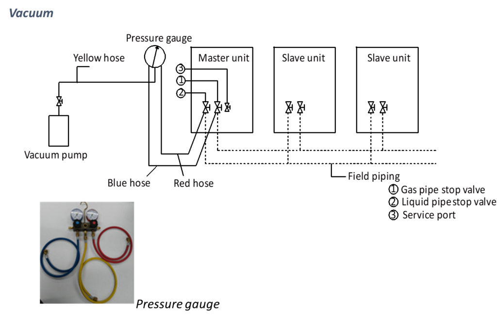
6.Vacuum
- Purpose: to remove moisture and non-condensable gases from the system.
- A vacuum pump capable of maintaining a pressure of -0.1MPa or lower should be used.
- Using a vacuum pump with a discharge in excess of 4L/s and a precision level of 0.02mmHg is recommended.
- Keep the liquid and gas stop valves fully closed.

- After Gas tightness test Insulation of remaining Joints to be done as below:
10. Charging Refrigerant
- Only charge refrigerant after performing a gastightness test and vacuum drying.
- Never charge more refrigerant than required as doing so can lead to liquid hammering.
- Only use refrigerant R410A, use tools and equipment designed for use with R410A.
- Always use protective gloves and protect your eyes when charging refrigerant.
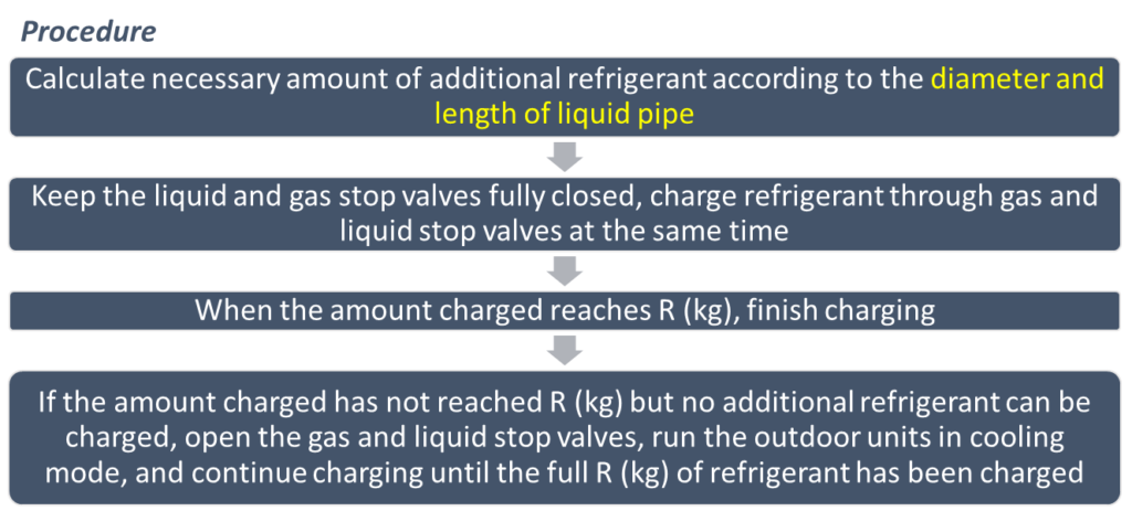
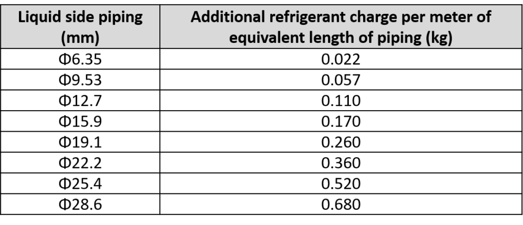
- The additional refrigerant charge required depends on the lengths and diameters of the outdoor and indoor liquid pipes.
- Assume 0.5m for the equivalent pipe length of each branch joint.

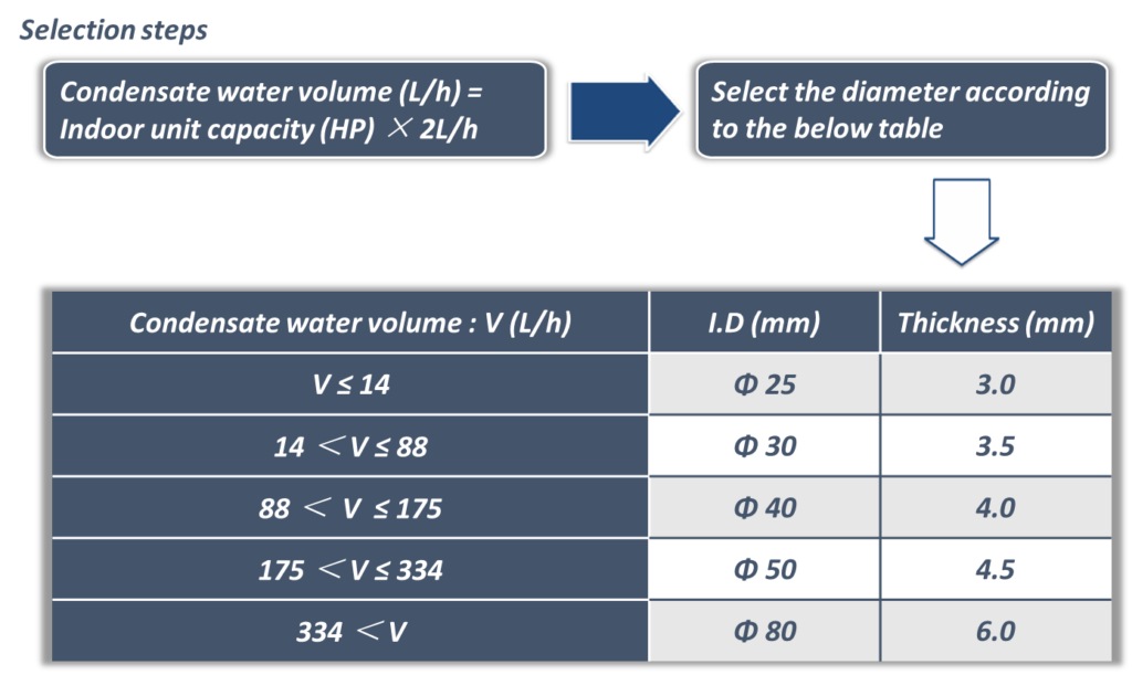
11. Drain Piping
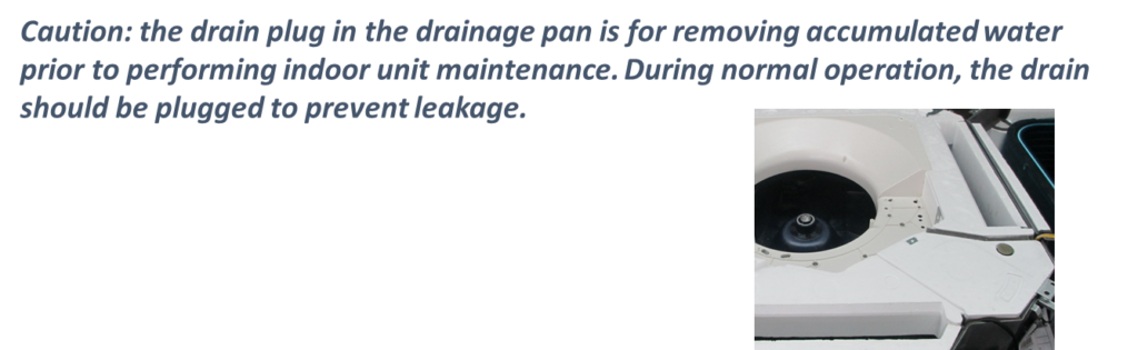
Caution:
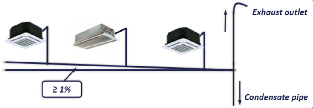
- The slope of main drain piping must be bigger than 1%.
- If the slope < 1%, then select drain piping with bigger diameter.
- The length of drain piping should be as short as possible.
- The drain piping should be independent with other water pipe. Never put the drain piping together with dirty water pipe.
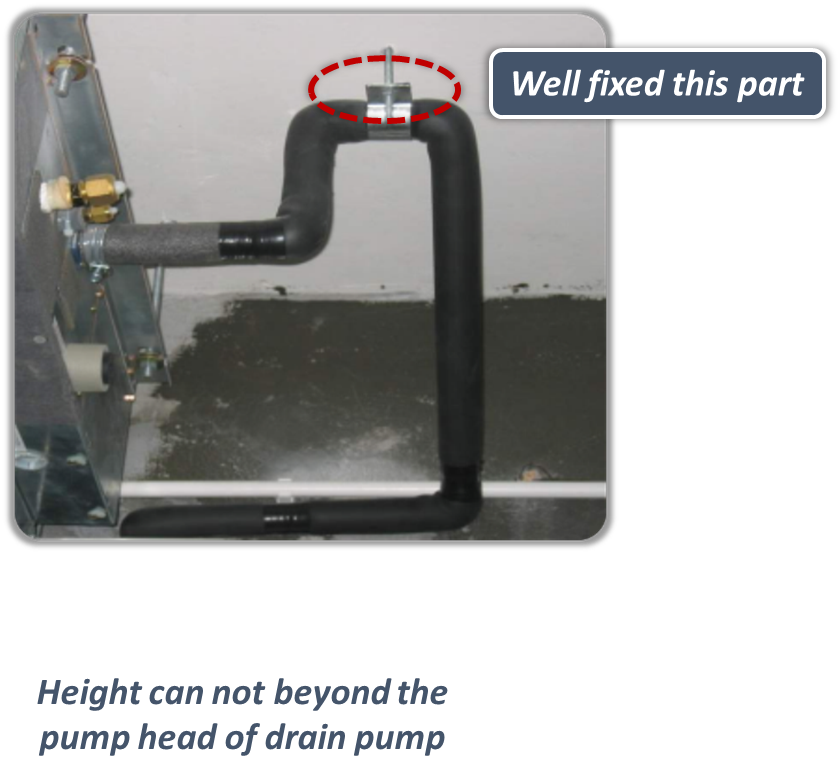
Discharge with drain pump:
- Some kinds of indoor units have built-in drain pump, the pumping head is 750mm at most.
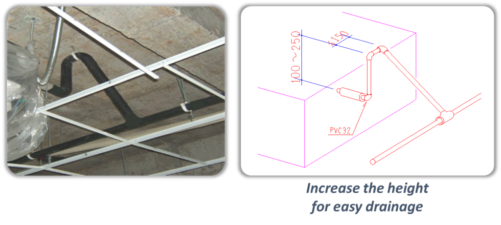
- Lifting the drainage pipe outlet to form the slope.
Natural drainage (without drain pump):
- If the pressure at the connection of the drain piping is negative, it needs to be fixed a drain trap.
- A plug should be designed to make cleaning easy.
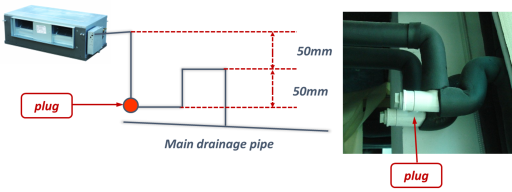
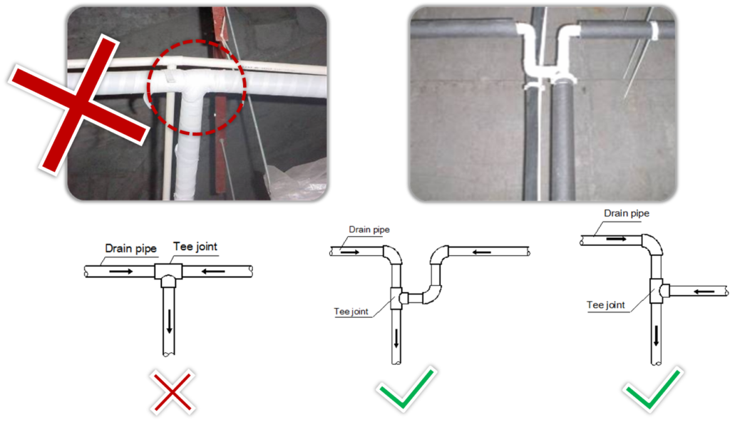
- To avoid the water flow back to the indoor unit, branch drain piping should join main drain piping from the top.
Drain Pipe Hanging
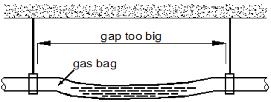
- To avoid the bending, recommended support/hanger spacing is 0.8 – 1.0m for horizontal piping and 1.5 – 2.0m for vertical piping.
- Each vertical section should be fitted with at least two supports. For horizontal piping, spacing greater than those recommended leads to sagging and deformation of the pipe profile at the supports which impedes water flow and should therefore be avoided.
- To avoid backflow and other potential complications, two horizontal drain pipes should not meet at the same level.
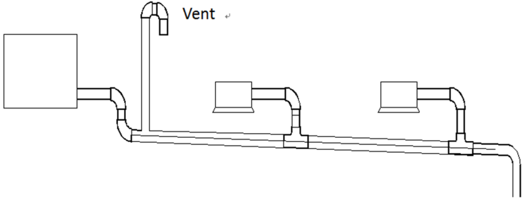
- Air vents should be fitted at the highest point of each drain piping system to ensure that condensation is discharged smoothly.
- U-bends or elbow joints should be used such that the vents face downwards, to prevent dust entering the piping.
- Air vents should not be installed too close to indoor unit lift pumps.
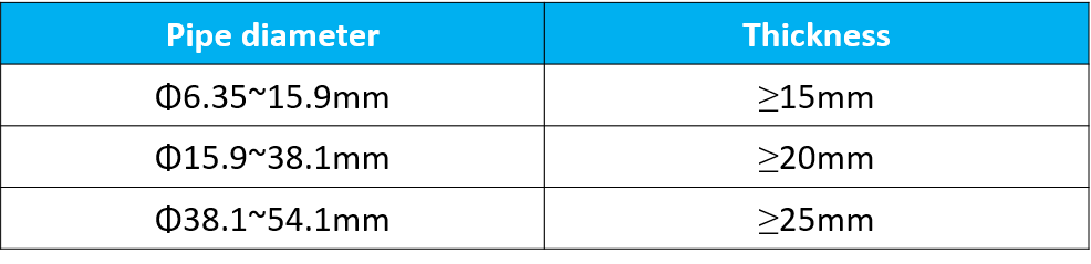
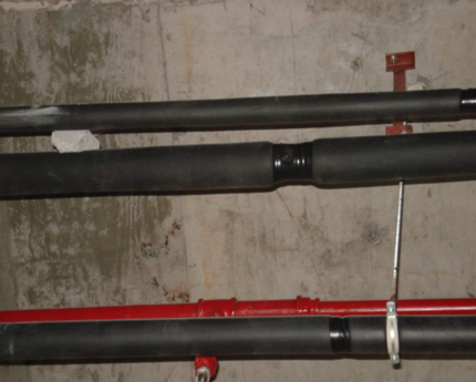
- Thermal insulation should be added to drain piping to prevent condensation forming. Thermal insulation should extend all the way to the connection with the indoor unit.
- The thickness of insulation material should be 10 to 13 mm.
- The gap between two pieces of insulation material should be filled with insulation material and then tape it.
Watertightness test and water flow test
- Watertightness test- Fill the piping with water and test for leakages over a 24-hour period.
- Water flow test (natural drainage test)– Slowly fill the drainage pan of each indoor unit with at least 600ml of water through the inspection port and check that the water is discharged through the outlet of the drain piping.
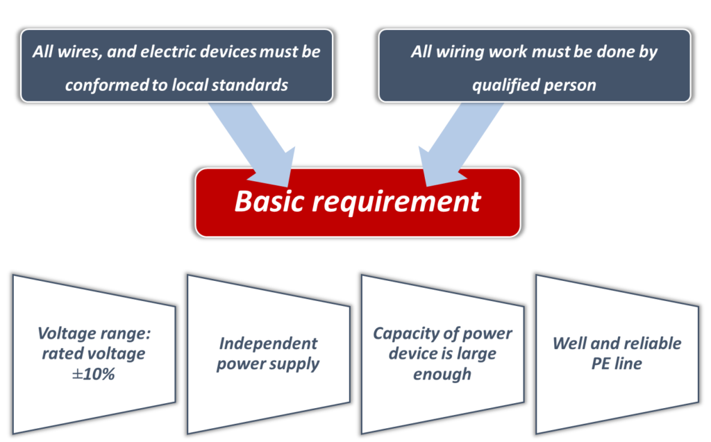
12.Electrical Power supply Wiring:
Power supply for outdoor unit
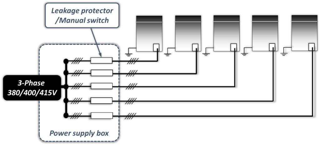
Power supply for indoor unit
- All the indoor units which connected to one outdoor system must be connected to one power supply
Why should all the indoor units which belong to one system have same power supply?
- If an indoor unit that is running were to suddenly power off whilst the other indoor units continued running, the evaporator of the powered-off unit would freeze since refrigerant would continue flowing to that unit (its expansion valve would still be open) but its fan would have stopped. The indoor units that remain running would not get sufficient refrigerant so their performance would suffer.
- Additionally, liquid refrigerant returning directly to the compressor from the powered-off unit would cause liquid hammering, potentially damaging the compressor.
Wire Size Selection:
- For indoor / outdoor unit power wire sizing and circuit breaker sizing, refer to indoor / outdoor unit “Electrical Characteristics” of respective machines as per manual provided by manufacturer.
- Select wire size based on the value of MCA in “Electrical Characteristics”.
- Select overcurrent circuit breakers and residual-current circuit breakers based on the value of MFA in “Electrical Characteristics”.
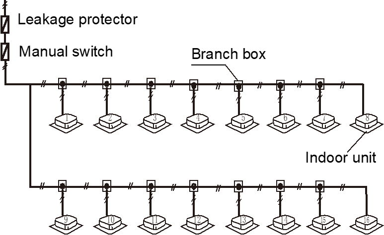
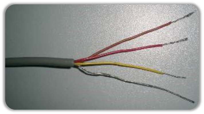
Communication wiring
- 0.75mm2 to 1.5mm2 3-core shielded cable is recommended for communication wiring. Using other types of cable can lead to interference and malfunction.

Communication wiring configurations – correct and incorrect examples.


Precautions:
- To prevent signal interference, the power wiring and communication wiring should not be run in the same conduit.
- If the power supply is less than 10A, a separation of at least 300mm between power wiring and communication wiring conduits should be maintained
- If the power supply is in the range 10A to 50A then a separation of at least 500mm should be maintained.
Done, we have discussed almost all the important point of VRF system Installation. For other field settings you can refer to manual of respective manufacturers.
Tnx for the impormation it is very helpfull
Aw, this was a very nice post. Taking the time and actual effort
to produce a great article… but what can I
say… I hesitate a whole lot and never manage to get nearly anything done.
My brother recommended I might like this website. He was entirely right.
This post truly made my day. You can not imagine simply how much time
I had spent for this info! Thanks! thesis writing